8 Resistors 2
In the box of miscellaneous electronic components, find a resistor having the bands:
- brown
- black
- red
- gold
Insert the resistor into the breadboard as shown below:
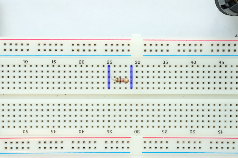
In the image above, the resistor leads are plugged into columns numbered \(25\) and \(29\). All of the holes in a single column (shown in blue) are connected. If we plug another connector into column \(25\) then that connector will be connected to the left lead of the resistor. If we plug another connector into column \(29\) then that connector will be connected to the right lead of the resistor.
Use the multimeter to measure the resistance of the resistor as shown below:
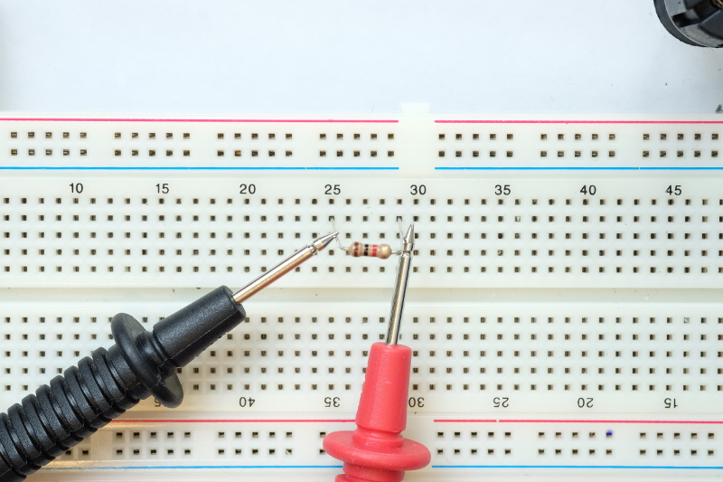
When you measure the resistance of the resistor make sure that the leads of the multimeter make firm contact with the leads of the resistor.
8.1 Record the measured resistance
Edit the script lab2.m and complete it so that the measured resistance of the resistor in ohms is stored in the variable R1. Note: the multimeter will probably report a value in kiloohms (\(k\Omega\)) or megaohms (\(M\Omega\)); you must convert the resistance to ohms.