22 Add more LEDs
On the breadboard, assemble 3 more resistor-LED circuits identical to the first circuit that you assembled. Using a jumper wire with alligator clips, connect the positive terminal of the LEDs to digital outputs 1 through 3 as shown in the image below:
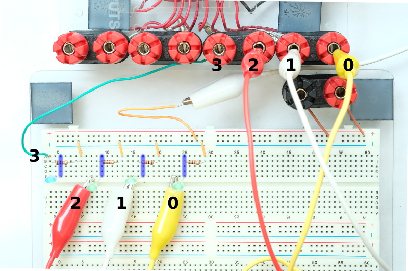
When assembling the additional circuits pay careful attention to make sure the negative terminal (shorter terminal) of each LED is connected to the resistor; in the image above, the resistors and negative terminals of the LEDS are plugged into columns 1, 9, 17, and 25.
Notice that we did not have a jumper wire with alligator clips to connect the left-most LED to digital output 3 of the Phidget. The positive terminal of the LED is plugged into column -1 and a plain jumper wire connects column -1 to the digital output 3 of the Phidget.
If you do not have enough jumper wires with alligator clips, use a plain jumper wire to make the connection. To connect the jumper wire to the digital output, unscrew the red plug at the digital output a few turns and insert the metal part of the wire into the gap created; tighten the plug to hold the wire in place and completing the connection. Make sure that the plug clamps down on only the metal part of the wire; no connection is made if the plug clamps down on the plastic insulator of the wire.