7 Setting up the Phidget and breadboard
Using the Phidget and the breadboard assemble the LED-resistor circuit from LAB 2. The LED will act as the device to be controlled by the Clapper.
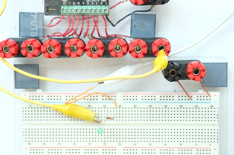
In the picture above, the white jumper wire is connected to the ground (GND) terminal of the Phidget. The yellow jumper wire is connected to the positive terminal of the LED (the longer terminal of the LED). The negative terminal of the LED and one terminal of the resistor are plugged into column 25.
Plug the USB-C to USB-A adapter into the computer.
Connect the Phidget to the computer using the USB cable. You must use the USB plug on the computer (not the ones on the monitor).
Plug in the USB cable of the webcam to the computer. You must use the USB plug on the computer (not the ones on the monitor).