CSE4431 Lab 04
Wood Shader 1
In this lab we will experiment with the wood shader from the textbook and
the slightly more sophisticated shader from the
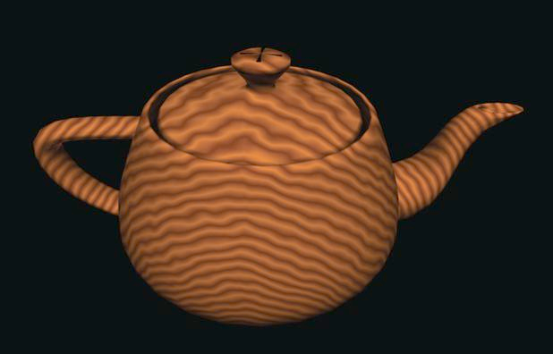
Wood is characterized by the rings that form as trees grow. These rings are something like the veins in marble, but rings have clearly defined edges between the light and dark wood, and the variation lies in the shape of the rings themselves. These are approximately cylindrical, with variation in their width and spacing. A wood fragment shader must try to capture those kinds of variations. In the figure below, we see an example of a wood shader applied to a teapot. This solid-texture wood shader operates by adding a noise value (based on the model-space coordinates of a point) to the distance from the modeling Y-axis, and uses that distance to mix the light and dark wood colors.
A wood fragment shader that implements this approach is shown below. This uses five uniform variables, three shader parameters and two color variables that control the ring colors and the parameters that simulate the rings. These could be used with glman as slider or color selection variables in a GLIB file to let you experiment with the colors and parameters to achieve the look you want in your shader. For example, you could use light colors and wide and fairly regular ring spacing to simulate pine.
One of the most common uses of a wood shader is to create wood surfaces
that model the look of wooden furniture or the like. We can see in the
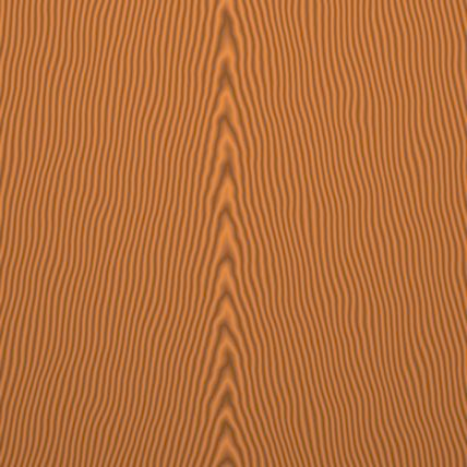
figure below that we can modify this shader to create the texture of a
wood surface (or, more precisely, a bookmatched veneer surface). This was
done by changing the expression for the dist variable by adding terms
as
sqrt(location.x * location.x + location.z * location.z) + sqrt(8. + location.y) + sqrt(8. + abs(location.x));
and, as before, note that
sqrt(location.x * location.x + location.z * location.z)
can be written more efficiently as
length(location.xy)
This gives roughly parallel structures on each side of the middle of the
surface. Other techniques for surfaces would consider the surface as a side
of a board (a modified cube) and would pick up the texture of the side as
part of the wood-textured solid.
glman Files
The glib file, vertex and fragment shaders for the teapot are shown below. Run the shaders in glman and try adjusting the sliders to observe the effects of the various parameters. If you study the fragment shader, you should realize that the pattern is constructed based on concentric rings; try to find values of the uniform variables that produce perfectly round rings (this might be easier if you change to the object from a teapot to an XY quadrilateral).
Try modifying the fragment shader so that it produces the V-pattern shown in the second image. Again, try adjusting the sliders to observe the effects of the various parameters. Try modifying this technique to produce different patterns.
Finally, if you do a google image search of "wood grain" you will find many examples of images of wood grain, some of which resemble the output of the given shader, and some which do not. Try modifying the shader to produce a different wood grain effect.
glib file
##OpenGL GLIB

GSTAP

Perspective 90
LookAt 0 0 3  0 0 0  0 1 0


Vertex   wood.vert
Fragment wood1.frag

Program  Wood1 \
uLightWoodColor {0.6 0.3 0.1 1.} \
uDarkWoodColor {0.4 0.2 0.07 1.} \
uRingFreq <0.0 10.0 20.0> \
uNoiseScale <0.0 0.25 1.0> \
uNoiseMag <0.0 1.0 2.0>

Rotate -90  1 0 0
Teapot
Vertex shader
This is just the ADS shader modified to produce the appropriate out variables.
#version 130

in vec4 aVertex;
in vec4 aNormal;

uniform mat4 uModelViewProjectionMatrix;
uniform mat4 uModelViewMatrix;
uniform mat4 uNormalMatrix;

out vec4 vLightIntensity;
out vec3 vMCposition;


// constants; would normally be uniforms

// light position in eye coordinates
const vec3 myLightPosition = vec3(1., 0.5, 0.);

const vec3 myLightAmbient = vec3(0.2, 0.2, 0.2);
const vec3 myLightDiffuse = vec3(1., 1., 1.);
const vec3 myLightSpecular = vec3(1., 1., 1.);

const vec3 myMaterialAmbient = vec3(1., 1., 1.);
const vec3 myMaterialDiffuse = vec3(0.7, 0.7, 0.7);
const vec3 myMaterialSpecular = vec3(0.3, 0.3, 0.3);
const float myMaterialShininess = 80.;

vec3 ADSLightModel(in vec3 myNormal, in vec3 myPosition)
{
  // normal, light, view, and reflection directions
  vec3 norm = normalize(myNormal);
  vec3 lightv = normalize(myLightPosition - myPosition);
  vec3 viewv = normalize(-myPosition);
  vec3 refl = reflect(-lightv, norm);

  // ambient
  vec3 ambient = myMaterialAmbient * myLightAmbient;

  // diffuse
  vec3 diffuse = max(0., dot(lightv, norm)) * myMaterialDiffuse * myLightDiffuse;

  // specular
  vec3 specular = vec3(0., 0., 0.);
  if (dot(lightv, viewv) > 0.)
  {
    specular = pow(max(0.0, dot(viewv, refl)), myMaterialShininess) *
               myMaterialSpecular * myLightSpecular;
  }
  return clamp(ambient + diffuse + specular, 0., 1.);
}

void main(void)
{
  // surface normal in eye coordinates
  vec3 normalE = vec3(uNormalMatrix * aNormal);

  // vertex position in eye coordinates
  vec4 vertexE = uModelViewMatrix * aVertex;
  vec3 positionE = vertexE.xyz / vertexE.w;

  vLightIntensity.rgb = ADSLightModel(normalE, positionE);
  vLightIntensity.a = 1.0;

  // model coordinates of vertex
  vMCposition = aVertex.xyz / aVertex.w;

  // transform the geometry
  gl_Position = uModelViewProjectionMatrix * aVertex;
}
Fragment shader
#version 130

uniform sampler3D Noise3;
uniform vec4      uLightWoodColor;
uniform vec4      uDarkWoodColor;
uniform float     uRingFreq;
uniform float     uNoiseScale;
uniform float     uNoiseMag;

in vec4 vLightIntensity;
in vec3 vMCposition;

out vec4 fFragColor;

void main()
{
   vec4 nv = uNoiseMag * texture(Noise3, uNoiseScale * vMCposition);
   vec3 location = vMCposition + nv.rgb;

   float dist = length(location.xy);
   dist *= uRingFreq;

   float t = fract(dist + nv.r + nv.g + nv.b) * 2.0;
   if (t > 1.0)
   {
      t = 2.0 - t;
   }

   vec4 color = mix(uLightWoodColor, uDarkWoodColor, t);
   color *= vLightIntensity;
   fFragColor = vec4(color.rgb, 1);
}
Wood Shader 2
The "OpenGL Shading Language" book contains a wood shader that is very similar to the previous shader, but it extends the previous shader to also produce the appearance of streaks that might have been caused by the wood having been cut with a saw; see the handout for details.
The glman and fragment shader are shown below. Again, try adjusting the sliders to observe the effects of the various parameters. The code used to generate the streaks is quite clever.
glib file
##OpenGL GLIB

GSTAP

Perspective 90
LookAt 0 0 3  0 0 0  0 1 0


Vertex   wood.vert
Fragment wood3.frag

Program  ADSvertex \
uLightWoodColor {0.6 0.3 0.1 1.} \
uDarkWoodColor {0.4 0.2 0.07 1.} \
uRingFreq <0.0 10.0 20.0> \
uLightGrains <0.0 1.0 1.0> \
uDarkGrains <0.0 0.0 1.0> \
uGrainThreshold <0.0 0.5 1.0> \
uNoiseScale <0.0 0.25 0.5> \
uNoiseMag <0.0 1.0 2.0> \
uGrainScale <0.0 20.0 40.0>

Cube
Fragment shader
#version 130

uniform sampler3D Noise3;
uniform vec4      uLightWoodColor;
uniform vec4      uDarkWoodColor;
uniform float     uRingFreq;
uniform float     uLightGrains;
uniform float     uDarkGrains;
uniform float     uGrainThreshold;
uniform float     uNoiseScale;
uniform float     uNoiseMag;
uniform float     uGrainScale;

in vec4 vLightIntensity;
in vec3 vMCposition;

out vec4 fFragColor;

void main()
{
   vec4 nv = uNoiseMag * texture(Noise3, uNoiseScale * vMCposition);
   vec3 location = vMCposition + nv.rgb;

   float dist = length(location.xz);
   dist *= uRingFreq;

   float t = fract(dist + nv.r + nv.g + nv.b) * 2.0;
   if (t > 1.0)
   {
      t = 2.0 - t;
   }

   vec4 color = mix(uLightWoodColor, uDarkWoodColor, t);

   t = fract((vMCposition.x + vMCposition.z) * uGrainScale + 0.5);
   nv.b *= t;
   if (t < uGrainThreshold)
      color += uLightWoodColor * uLightGrains * nv.b;
   else
      color -= uLightWoodColor * uDarkGrains * nv.b;

   color *= vLightIntensity;
   fFragColor = vec4(color.rgb, 1);
}